Help Calculating Length And Position Of Connections On Rotating Object

  • #1
carman435
29
2
Homework Statement
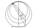
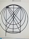
Calculate the position and length lines A & B would be to allow for a full rotation into the opposite position.
Relevant Equations
I'm really unsure! I'm currently looking into four bar linkage but I am not sure it is relevant
Hi, i need to find a formula or calculation that would allow me to connect three lines when rotating. The three lines must fall so that they mirror themselves on the opposite side.

I need to be able to calculate this for now just the example above but be able to apply to a range of lengths and heights.

Any help in terms of connecting three rotating objects would be nice as I'm at a total loss here.
 

Attachments

  • Drawing 1.png
    Drawing 1.png
    17.6 KB · Views: 1
Physics news on Phys.org
  • #2
Welcome to PF.

Sorry, but I don't follow your description.
What three lines rotate? About which axis, the same or different axes?
Which lines are A and B ? How are the lines connected?
carman435 said:
The three lines must fall so that they mirror themselves on the opposite side.
On the opposite side of what?
 
  • #3
Baluncore said:
Welcome to PF.

Sorry, but I don't follow your description.
What three lines rotate? About which axis, the same or different axes?
Which lines are A and B ? How are the lines connected?

On the opposite side of what?
Hi sorry its my first time and I don't think I've been very clear. Here's another clearer drawing.

Point 4 will move to d
point 5 to e
point 6 to f

Point 1 will drop to a
Point 2 to b
Point 3 to x

I need them to do this in tandem. When the bottom line is move all three need to move equally. I'm trying to connect the three lines by attaching a connector from 1,4 to 2,5 and a connector from 2, to 3, 6
I'm not sure where to place the connectors so that they rotate without getting stuck nor am I sure what length they need to be. I have no idea where to even being in terms of looking for math to help this.


I hope that helps and thankyou for any help you give.
 

Attachments

  • 20240428_134246.jpg
    20240428_134246.jpg
    40.6 KB · Views: 2
  • #4
I assume this is a 2D problem.

Draw each line in its initial and final position. Where the lines cross themselves, could be a stationary point on the line, as it rotates.

Those three stationary points could be connected with fixed length connections.

If you could identify the correct question, you could answer it yourself.
We must find the correct question to get the right answer.
 
  • #5
Baluncore said:
I assume this is a 2D problem.

Draw each line in its initial and final position. Where the lines cross themselves, could be a stationary point on the line, as it rotates.

Those three stationary points could be connected with fixed length connections.

If you could identify the correct question, you could answer it yourself.
We must find the correct question to get the right answer.
It is a 2d problem.

I'm sorry but I'm not sure I understand?.

Ive drawn the lines in the opposite position but they just cross themselves in the centre line which is the centre of rotation.

They do overlap each other as they rotate however if thats what your reffering to? I.e 1,4 is overlapped by 2,5 on its journey so is that where I'd place the first connector?

I'm really unsure of the maths around this as it's a bit out of my depth really. So I'd appriciate any direction you can give at all.

Is there any reading you could suggest or a maths terms for what this is called so I can try and research it a bit to understand the fundamentals?
 
  • #6
We still do not have a formulation of the problem.
Where does this problem come from?
Do you have a link to the original?

I am assuming that the lines all rotate together, a bit like a parallel ruler, and that is why you want to connect and discipline them.
https://en.wikipedia.org/wiki/Parallel_rulers
This then becomes a transformation mapping problem, with a single parameter that represents time.

Are the lines all attached to a common axis somewhere?

Are the lines = links with fixed lengths, or defined as infinite, passing through two points P(x,y)?
 
  • #7
Baluncore said:
We still do not have a formulation of the problem.
Where does this problem come from?
Do you have a link to the original?

I am assuming that the lines all rotate together, a bit like a parallel ruler, and that is why you want to connect and discipline them.
https://en.wikipedia.org/wiki/Parallel_rulers
This then becomes a transformation mapping problem, with a single parameter that represents time.

Are the lines all attached to a common axis somewhere?

Are the lines = links with fixed lengths, or defined as infinite, passing through two points P(x,y)?

I don't have a link to the original unfortunately it's something I've been asked to look over by a friend. I have asked for more info but he hasn't responded yet. I think it's something for his college work but I'm unsure.

The lines are all connected to a common axis which is the centre line. This is what they must all go through as the rotation is centred around this.

I will outline the position of each.

The top line is 1891.9
The middle line is 2347
The bottom line is 2829.735

I need to create three rotating points, that go through the following positions.

1450,100 - 0, 2520
1450,600 - 100, 2520
1450, 1100 - 200, 2520

These lines should pass through a horizontal line in the centre which will be the point they rotate around.

I need to connect these points using a formula that can then be repeated for any other dimensions required using the above information.

I hope that clears it up
 
  • #8
I still have too many possible interpretations of the details.
carman435 said:
I will outline the position of each.
The top line is 1891.9
The middle line is 2347
The bottom line is 2829.735
How can a line be positioned with one number? Relative to what?
carman435 said:
I need to create three rotating points, that go through the following positions.
1450,100 - 0, 2520
1450,600 - 100, 2520
1450, 1100 - 200, 2520
Is the ',' a decimal point or a separator.
Is the '-' a separator or a negative sign.

Maybe you could update the diagram you gave in post #3.
Please label the axes and mark the origin.
Identify the coordinates of points 1 to 6, and A to F.
Mark the centre of rotation of each line.
 
  • #9
Baluncore said:
I still have too many possible interpretations of the details.

How can a line be positioned with one number? Relative to what?

Is the ',' a decimal point or a separator.
Is the '-' a separator or a negative sign.

Maybe you could update the diagram you gave in post #3.
Please label the axes and mark the origin.
Identify the coordinates of points 1 to 6, and A to F.
Mark the centre of rotation of each line.

Hi ive updated it to the best of my ability. I usually use Cad to do this sort of thing so the drawings a bit rough and not to scale at all. But it should show what I'm trying to achieve.

Thanks again for your help.
 

Attachments

  • 20240428_155751.jpg
    20240428_155751.jpg
    23.4 KB · Views: 2
  • #10
carman435 said:
Hi ive updated it to the best of my ability. I usually use Cad to do this sort of thing so the drawings a bit rough and not to scale at all. But it should show what I'm trying to achieve.

Thanks again for your help.

To add to this the , is a separator so the coordinates would be Horizontal 0 Vertical 2520
 
  • #11
The lines all have different lengths: 2029.507, 2347.104, 2723.765
The lines all have different slopes: -44.401°, -54.887°, -62.682°

We know the lines rotate about three points on a common vertical line. We do not know the x coordinate of that line, so we cannot find the coordinates of the centres of rotation.
 
  • #12
Baluncore said:
The lines all have different lengths: 2029.507, 2347.104, 2723.765
The lines all have different slopes: -44.401°, -54.887°, -62.682°

We know the lines rotate about three points on a common vertical line. We do not know the x coordinate of that line, so we cannot find the coordinates of the centres of rotation.
Sorry, so the line that they rotate around is positioned at half way along the horizontal axis.

So for this one it would 725
 
  • #13
Line lengths: 2029.507; 2347.105; 2723.766
Line slopes: -44.401; -54.888; -62.682
Rotation centres:
(725.000, 1810.000); (725.000, 1631.111); (725.000, 1503.600)

Now we know what the lines rotate about, we can rotate them by some amount. How will that rotation be specified?

What output do you need during, or finally, from that rotation?
 
  • #14
Baluncore said:
Line lengths: 2029.507; 2347.105; 2723.766
Line slopes: -44.401; -54.888; -62.682
Rotation centres:
(725.000, 1810.000); (725.000, 1631.111); (725.000, 1503.600)

Now we know what the lines rotate about, we can rotate them by some amount. How will that rotation be specified?

What output do you need during, or finally, from that rotation?

So I need them to rotate so they fall into the opposite position.

So the points move from

0, 2520 to 0, 100
100, 2520 to 0, 600
200, 2520 to 0, 1100

I think it's a rotation of maybe 90 degrees?
 
  • #15
carman435 said:
I think it's a rotation of maybe 90 degrees?
It will be something like that.
Do you want to know where the ends of the lines will be after the rotation?
 
  • #16
Baluncore said:
It will be something like that.
Do you want to know where the ends of the lines will be after the rotation?

It doesn't matter how long they are along as they turn and fall into the opposite position. The point 0,2520 becomes 0, 100

Along as that happens alongside the same rotation same rotation for the other two the length is irrelevant. What I need is how to connect them so they rotate in this way
 
  • #17
I will assume the centres of rotation are fixed pins that the bars=lines rotate about. Boiling the problem down; we need to find points on the bars, that are the same distance apart at the start and at the end of the rotation.
Yes, the mechanism is a four bar linkage.
Because the bars are not parallel, the connecting links will not be parallel with the y-axis.
Picking a point on one bar, should determine the point on the adjacent bar that should be connected.
I will need to think about it.
 
  • #18
Baluncore said:
I will assume the centres of rotation are fixed pins that the bars=lines rotate about. Boiling the problem down; we need to find points on the bars, that are the same distance apart at the start and at the end of the rotation.
Yes, the mechanism is a four bar linkage.
Because the bars are not parallel, the connecting links will not be parallel with the y-axis.
Picking a point on one bar, should determine the point on the adjacent bar that should be connected.
I will need to think about it.

I see thankyou for going through all this with me.

I think if they were parallel it would be a much easier time. Unfortunately they cannot be. If I'm not mistaken the connecting pieces would also need to rotate to almost 'fall' in line with the bars as they move up and then open back up as they come down.

Again thankyou for the time you've put into this for me. I have no idea why you've given me this kindness but it's appreciated. I'm going to spend the evening learning about four bar linkage and seeing if I can find any examples similar to this I'm facing now.

Complicated but I'm sure it's possible!
 
  • #19
As a follow up to this. I've looked a tad at four bar linkage. I believe a set of constants would help, if I were to decide on a a point across each each bar. Say 100 in from the point 1450, 100 etc etc. Then use this as the first point of my linkage I believe using the angles of the bars at these points I should have sufficient information to create a three bar linkage which I think this actually is.

I think it's two sets of interconnected three bar linkages. No idea how that works but I'm going to have a go. Thanks for your help. If you get any idea of how to calculate this I'd love to hear it.
 
  • #20
carman435 said:
As a follow up to this. I've looked a tad at four bar linkage. I believe a set of constants would help, if I were to decide on a a point across each each bar. Say 100 in from the point 1450, 100 etc etc. Then use this as the first point of my linkage I believe using the angles of the bars at these points I should have sufficient information to create a three bar linkage which I think this actually is.

I think it's two sets of interconnected three bar linkages. No idea how that works but I'm going to have a go. Thanks for your help. If you get any idea of how to calculate this I'd love to hear it.

As a further follow up. I think it's actually two sets of four bar linkages.

I believe if I can set a constant on the upper bar as a point of connection. I can calculate the linkage required to connect to the middle bar.

I can then set a similar constant on the middle bar and connect to the lower bar. Along as these don't adjust the rotation of the bars which they shouldn't it shouldn't really matter where I set my constants I believe. Along as I get the formulas right I believe I can calculate them independently of each other.
 
  • #21
The line between two centres of rotation is a bar, so it is a 4 bar linkage.

It is easy to pick a point on the first bar. The difficulty is finding the point on another bar that is separated by the same distance in both end positions. You need to solve a system of equations to find both the distance along the second bar, and the length of the connecting link.
 
  • #22
Baluncore said:
The line between two centres of rotation is a bar, so it is a 4 bar linkage.

It is easy to pick a point on the first bar. The difficulty is finding the point on another bar that is separated by the same distance in both end positions. You need to solve a system of equations to find both the distance along the second bar, and the length of the connecting link.

I'm assuming there isn't a standard formula that uses the length of the bars and the angle to find an appropriate linkage?
 
  • #23
carman435 said:
I'm assuming there isn't a standard formula that uses the length of the bars and the angle to find an appropriate linkage?
Not in this case, since the end-points of the rotation are not directly defined. The solution to linkage problems often comes down to the intersection of two circles.
 
  • #24
Baluncore said:
Not in this case, since the end-points of the rotation are not directly defined. The solution to linkage problems often comes down to the intersection of two circles.

Ah the end points of the rotation are defined. I think?

The points should rotate until they fall into their opposite positions. Point 0,2520 will rotate into position 0,100

If they were defined how would I calculate the linkage would it be at the points of intersection?
 
  • #25
carman435 said:
The points should rotate until they fall into their opposite positions.
Yes, but that is not a simple thing.

carman435 said:
If they were defined how would I calculate the linkage would it be at the points of intersection?
The solution of two equations, or the numerical search of a line for a minimum difference in the separation before and after.

https://www.braingle.com/brainteasers/17877/miracle-mountain.html
 
  • #26
I think I'm confusing things here.

Effectively what I'm looking for is the formula to calculate the coupling position and the lengths they are.

The starting points of the rotation shouldn't matter for me as I can adjust them in the formula (I think)

The end points again shouldn't matter. If I'm not mistaken the end and starting points should be variables that can be set in the equation, or will directly result in creation of the variables for the formula.

The rotation will always be from points
0, 100 to 0,2520
0, 600 to 100, 2520
0, 1100 to 200, 2520
And then the inverse on the opposing side

1450, 2520 to 1450, 100
1350, 2520 to 1450, 600,
1250, 2520 to 1450, 1100

The lines when drawn require an adjustment to start and end at these points. The way I've mapped them is by drawing the points from 0,100 to 0,2520 then I've taken the half way point of this line, drawn a line in the opposite angled position towards the centre line situated at 725 on the horizontal axis. The point this line intersects the centre line is The rotation point. I've attached a photo of this to help explain it as I feel I'm not very good at explaining what I'm talking about.

So the lines don't intersect the centre axis at their middle. If that makes sense. The middle piece of each line has a line coming down to connect it to the centre axis, this is to make the rotation change so that they fall into the same positions each way.

The drawing below may help. It shows both sides at once in all positions
 

Attachments

  • 20240428_204751.jpg
    20240428_204751.jpg
    43.9 KB · Views: 1
  • #27
Baluncore said:
Yes, but that is not a simple thing.

I know it's not a simple thing but I believe I have accurately managed this piece in Cad, I think I can reflect my actions in a formula if given time

The solution of two equations, or the numerical search of a line for a minimum difference in the separation before and after.

https://www.braingle.com/brainteasers/17877/miracle-mountain.html

What two equations would they be? Would you know the names or where I could find them?
 
  • #28
carman435 said:
I think I'm confusing things here.
... and very much so, I would add. :oops:
I have been following your descriptions of the mechanism, but I get more and more confused.

Are those rotating lines gates?
Do the diagrams show a plan view?
Could you show an elevation view?

Why is not the smallest circle concentric to anything?
How can the lines not collide with each other when on the same plane?
How will the links not collide with the rotating lines?
 
  • Like
Likes berkeman
  • #29
  • #30
Yes sorry. I tend to babble and get people confused a lot. Poor trait but I'm working on it !

The view we are seeing is a side view. The reason they won't hit each other is that they won't do a full rotation around the axis. I've simply put the circles on as I was trying to visualise it.

The arc of the top line will stop at the position at 1250, 2520 and go no higher.

The links will not collide as they will be directly attached to the rotating lines. Not sure if that answers that question to be honest!
 
  • #31
As for a plan view or an elevated view. This is a 2d rotational model I've been asked for help with. My friend believes they have other working models which they use to test things before furthering development but I'm being given limited info here
 
  • #33
Here's another photo showing just the arcs and there limit. It does not show the entire circle. Just the arcs the lines will follow
20240428_210847.jpg
 
Last edited by a moderator:
  • #34
carman435 said:
Ah okay, does the above info help at all
Not really, it just confuses more.
I understand the problem, and have sufficient information.

There is no point hitting my head against it now. I will be driving for an hour or two later, which will be plenty of time to relax the problem, and hopefully see an elegant solution.
 
  • #35
Baluncore said:
Not really, it just confuses more.
I understand the problem, and have sufficient information.

There is no point hitting my head against it now. I will be driving for an hour or two later, which will be plenty of time to relax the problem, and hopefully see an elegant solution.

Thanks. I appriciate your help in this. I will stop supplying info as I get the impression I'm no help here at all!.

Thanks for your help and time
 

Similar threads

  • Engineering and Comp Sci Homework Help
Replies
7
Views
3K
  • Engineering and Comp Sci Homework Help
2
Replies
49
Views
3K
  • Engineering and Comp Sci Homework Help
Replies
1
Views
990
  • Engineering and Comp Sci Homework Help
Replies
8
Views
1K
  • Introductory Physics Homework Help
Replies
33
Views
1K
  • Engineering and Comp Sci Homework Help
Replies
9
Views
2K
  • Introductory Physics Homework Help
Replies
17
Views
764
  • Engineering and Comp Sci Homework Help
Replies
6
Views
2K
  • Atomic and Condensed Matter
Replies
0
Views
428
  • Engineering and Comp Sci Homework Help
2
Replies
40
Views
4K
Back
Top